
| Page 2 | Experiments Menu | Teralab Main Menu |
|---|
Practical gas discharge tubes are filled with noble gases. The most common filling being neon. The noble gases appear in the far right hand column of the periodic table. Their atoms have full outer shells and as a result are chemically inert.
Unfortunately, gas filling a discharge tube is rather more difficult and complicated than simply pumping the air pressure down to the glow region. Firstly a gas supply is required. I decided to use the helium cylinder from a 'Box O Balloons' kit. This had the advantages that it was cheap, easily available and had a low bottle pressure. The disadvantage is that the gas is of dubious purity.
Next a method of controlling the gas flow is required. Connecting the discharge tube directly to bottle pressure would be very dangerous. I reduced the gas pressure down to 1 bar gauge (2 bar absolute) using a Spirax Monnier MR2 regulator scavenged from an old pneumatic controller. The MR2 has a maximum inlet pressure of 21 bar. The helium bottle is 29 bar full (ahem). I followed that with a needle valve to control the flow rate. The outlet of the needle valve feeds into the gas discharge tube and the rotary vacuum pump. A schematic diagram is shown below.
There are two possible operating methods; static and dynamic.
The static method starts with the regulator set to 1 bar, all valves shut and the pump running. The needle valve and pump valves are then fully opened to evacuate everything up to the valve on the cylinder. The needle valve and pump valve are then closed and the valve on the cylinder is opened. The needle valve is then slightly opened until the desired filling pressure is reached and then closed again.
The dynamic method compensates for small leaks and also tends to flush through unwanted gases. The process starts with the regulator set to 1 bar, all valves shut and the pump running. The needle valve and pump valves are then fully opened to evacuate everything up to the valve on the cylinder. The needle valve is then closed and the valve on the cylinder is opened (the pump valve is kept open). The needle valve is then adjusted to give the desired pressure. In this mode, gas flows continuously through the system.
In the picture below, the dynamic method is being used with the tube pressure set at 1 mbar. The characteristic pink glow of helium can be seen in the discharge tube.
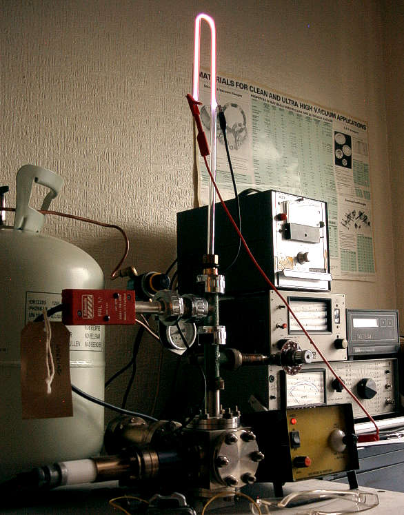
In the far left of the picture above, the gray helium cylinder can be seen. This is connected to the regulator by a thin length of copper tube. The regulator is the small green device with the yellow ring. The needle valve is just above the yellow front panel of the high voltage power supply. The vacuum pump is lower down, out of the picture.
| Page 2 | Experiments Menu | Teralab Main Menu |
|---|