
| Experiments Menu | Teralab Main Menu |
|---|
The aim of this experiment was to construct an electron gun completely from scratch. The ultimate goal was to produce a video image inside the bell jar of the vacuum rig.
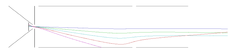
Electrostatic focusing and deflection was chosen, as large coils of wire would trap air and so be incompatible with the high vacuum environment. For the design of the gun some simulation software was desirable. CPO-2D student version was used. This software can be downloaded free from CPO Ltd. The student version is limited to a maximum of five electrodes, but is still very useful.
Above is a typical graphical output from CPO-2D. From left to right, the electrodes are grid (-1010V), cathode (-1000V), first anode (0V), focus (-800V), final anode (0V).
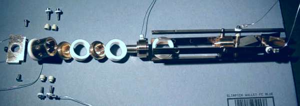
The electrodes were machined from brass on an Emco Unimat 3 lathe. The insulators for the grid cylinder were turned from Macor rod. Macor is a machinable ceramic. It is expensive and difficult to machine, but is ideal for vacuum work and can operate at 1000C. This part of the gun will get very hot in operation because the cathode is directly heated tungsten wire.
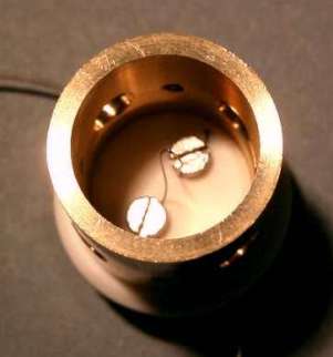
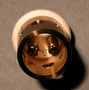
When the gun was first operated, the cathode twisted and became misaligned with the grid aperture. To overcome this problem, a shorter cathode was mounted on pillars. The twisted cathode can be seen in the left hand photo above and the modification in the right hand photo. The holes in the sides of the cylinder are to allow gas to escape.
In the above photograph, the gun can be seen largely dismantled during modification of the cathode.
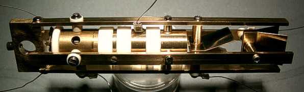
This is the completed electron gun. The block with a hole through it on the far left is for mounting the electron gun assembly on the vacuum rig jigging. To test the gun, a phosphor screen was required. The face plate was cut from an old oscilloscope tube using a diamond disc cutter (RS part 182-887).
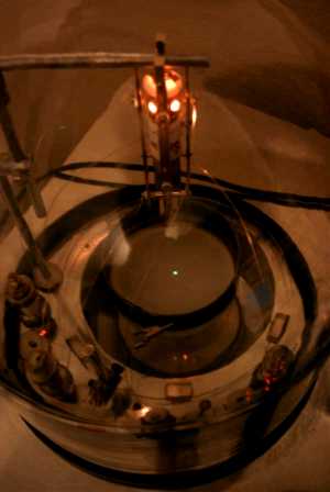
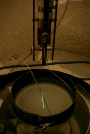
In the above photos, the gun was operating in the vacuum bell jar. The cathode was at -1713V and the focus voltage was -1367V. The cathode was operating at 4.3A dc. Because the cathode is directly heated, ac heater current was found to modulate the emission, causing an out of focus spot. Direct current therefore had to be used to heat the cathode. In the above left photo, all deflection plates were at 0V, giving a spot in the middle of the screen. The cathode can be seen glowing at the top of the picture. In the above right photo, the spot was scanned to produce a line. The deflection voltage was 170Vpp.
I am now designing deflection amplifiers and time bases to sweep the spot. With the addition of a video amplifier it should be possible to display a video image. I also plan to replace the face plate with something home made. Using the face plate from an oscilloscope tube seems like cheating.
| Experiments Menu | Teralab Main Menu |
|---|