
| Electronics Menu | Teralab Main Menu |
|---|
This project is a very simple spot welder which will weld thin sheet metal. It will just about weld 0.38mm thick steel. Sheet steel half this thickness welds effortlessly. It can be used for assembling high vacuum components and making thermocouples.
WARNING: Despite the simplicity of this design, it can be quite hazardous. Goggles must be worn when using it. High temperature is produced during operation which could cause burns. There is also the hazard of mains voltage internally.
Click on the schematic below to see it in higher resolution. This is the basic welder circuit with only the essential components shown. The relay RL1 is a Crydom D2425 solid state relay. The low voltage dc controlled version has been used so that controlling it with a remote foot switch (S1) is safe. T2, D1 and C1 provide the control voltage for the solid state relay. There is obviously plenty of scope for variation and improvement of this design. A worthwhile enhancement would be the addition of a timer to control the duration of the weld.
T1 uses a transformer removed from a microwave oven. Please be aware that the power supply in a microwave oven is absolutely lethal. Do not switch the oven on with the cover removed and do not apply power to the transformer until the secondary has been removed. Make sure that the oven has been unplugged from the supply for at least an hour before removing the cover.
The transformer T1 is the special bit. It is a modified microwave oven transformer. Remove the transformer from an old oven (not the one from your mothers kitchen). There should be separate windings side by side. Saw off the exposed parts of the secondary windings taking great care not to damage the primary. Drive out the rest of the secondary wire with a hammer and chisel. Wind about ten turns of insulated copper wire into the space where the secondary used to be. This wire can be quite thin. It is temporary and will not become the welding winding. Connect an ac voltmeter to this new secondary. Make the transformer electrically safe by covering all exposed mains wiring and connect the primary to the mains supply. Switch off and Reduce or increase the number of turns on the secondary to get about 4Vrms. Unwind the temporary secondary whilst counting the number of turns. Insulate a length of copper braid with shrink sleeve. I used tin plated copper braid which is 11mm wide and 1.6mm thick. Wind the insulated braid as the new secondary with the correct number of turns to get 4Vrms.
I mounted most of the components on a side panel from an old subrack. All exposed metal parts must be earthed.
It would be worth adding an adjustable timer to control weld duration. A timer adjustable from 0.05s to 5s would be of great assistance in obtaining consistent welds. The welder could also be powered from an external Variac (variable auto transformer) to control the welding power.
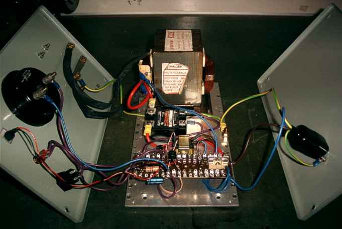
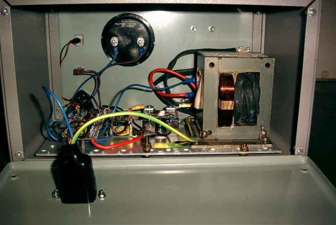
The baseplate fits inside the steel case. The mains enters via an IEC connector on the rear panel. The microwave transformer can be seen on the right-hand side of the photograph below. The left-hand winding is the primary and the right-hand winding is the copper braid secondary. The solid state relay is the black box, just to the left of the big transformer. The baby transformer just to the left of the relay is for the relay control voltage. The primary of this transformer is separately fused at 250mA.
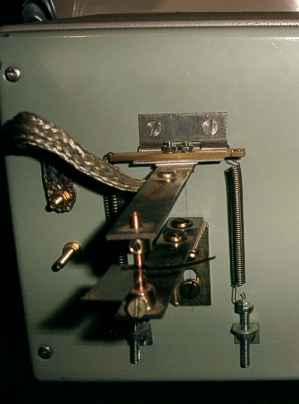 The welding
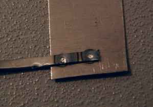
arms are made from mild steel. This may not be ideal; they warm up during use. The bottom
one is fixed to the front panel with a 90 degree bracket. The top one is mounted on a
hinge. The hinged electrode arm is insulated from the chassis by a sheet or PTFE. It can
just be seen as a white line between the steel arm and the hinge.
The welding
arms are made from mild steel. This may not be ideal; they warm up during use. The bottom
one is fixed to the front panel with a 90 degree bracket. The top one is mounted on a
hinge. The hinged electrode arm is insulated from the chassis by a sheet or PTFE. It can
just be seen as a white line between the steel arm and the hinge.
The electrodes are turned from copper. The top one has a 90 degree cone tip. The bottom one
has a flat top to make the alignment less critical. The arms are pulled together by a pair
of springs.
The upper arm is connected to the transformer secondary by a short length of copper braid
and an M4 bolt which is insulated from the front panel.
The bottom arm is connected to the other end of the transformer secondary via the bolts
which hold the bracket to the front panel. The bottom arm is also connected to mains
earth.
First power the unit up with a piece of cardboard between the welding electrodes. Connect an ac voltmeter between the electrodes. There should not be any voltage. Press the weld button or foot-switch. If the circuit is working properly there should be a hum from the transformer and 4Vrms across the welding electrodes. The voltage should drop back to zero when the switch is released.
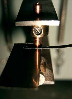 Brass
cylinders are brazed to the welding arms. These hold the copper electrodes, which are each
secured by a screw.
Brass
cylinders are brazed to the welding arms. These hold the copper electrodes, which are each
secured by a screw.
Two pieces of 0.17mm thick stainless steel are held between the electrodes ready for the
first test.
Pressing the foot switch give a buzz from the transformer, an orange glow from the tips
of the electrodes and a little wisp of smoke.
 This is the
resulting stainless steel test weld. I have also tried welding tantalum and it works very
well. The only problem with welding tantalum is that it glows white hot. It is so bright
that it is painful on the eyes.
This is the
resulting stainless steel test weld. I have also tried welding tantalum and it works very
well. The only problem with welding tantalum is that it glows white hot. It is so bright
that it is painful on the eyes.
Appropriate eye protection should obviously be used when welding materials with very high
melting points. Ordinary safety goggles should be adequate when spot welding steel.
| Electronics Menu | Teralab Main Menu |
|---|